
Published by: Zaya
Published date: 26 Jun 2021
In the previous Power Diodes tutorial, we discussed ways of reducing the ripple or voltage variations on a direct DC voltage by connecting smoothing capacitors across the load resistance.
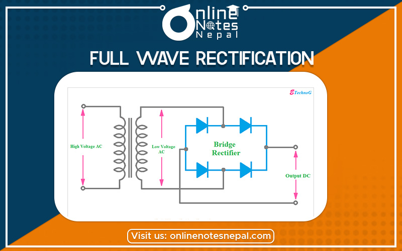
While this method may be suitable for low power applications it is unsuitable to applications that need a “steady and smooth” DC supply voltage. One method to improve on this is to use every half-cycle of the input voltage instead of every other half-cycle. The circuit which allows us to do this is called a Full Wave Rectifier.
Like the half-wave circuit, a full-wave rectifier circuit produces an output voltage or current which is purely DC or has some specified DC component. Full-wave rectifiers have some fundamental advantages over their half-wave rectifier counterparts. The average (DC) output voltage is higher than for half-wave, the output of the full-wave rectifier has much less ripple than that of the half-wave rectifier producing a smoother output waveform.
In a Full Wave Rectifier circuit, two diodes are now used, one for each half of the cycle. A multiple winding transformer is used whose secondary winding is split equally into two halves with a common center-tapped connection, (C). This configuration results in each diode conducting in turn when its anode terminal is positive concerning the transformer center point C producing an output during both half-cycles, twice that for the half-wave rectifier so it is 100% efficient as shown below.
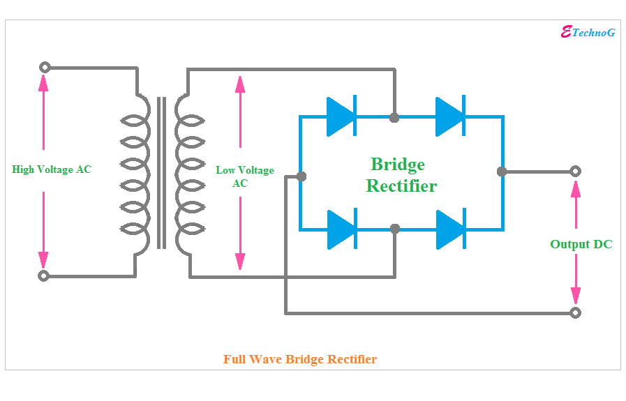
The full-wave rectifier circuit consists of two power diodes connected to a single load resistance (RL) with each diode taking it, in turn, to supply current to the load. When point A of the transformer is positive concerning point C, diode D1 conducts in the forward direction as indicated by the arrows.
When point B is positive (in the negative half of the cycle) concerning point C, diode D2 conducts in the forward direction and the current flowing through resistor R is in the same direction for both half-cycles. As the output voltage across the resistor R is the phasor sum of the two waveforms combined, this type of full-wave rectifier circuit is also known as a “bi-phase” circuit.
Full-wave Rectifier with Smoothing Capacitor
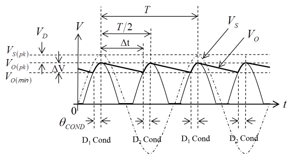
The smoothing capacitor converts the full-wave rippled output of the rectifier into a more smooth DC output voltage. If we now run the Partsim Simulator Circuit with different values of the smoothing capacitor installed, we can see the effect it has on the rectified output waveform as shown.