
Published by: Zaya
Published date: 26 Jun 2021
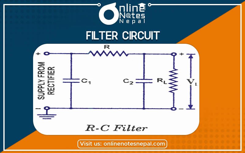
To remove the AC components or filter them out in a rectifier circuit, a filter circuit is used. A filter circuit is a device to remove the A.C components of the rectified output but allows the D.C components to reach the load. A filter circuit is, in general, a combination of the inductor(L) and Capacitor that allows A.C only and the inductor allows D.C only to pass. So only to pass. So a suitable L and C network can effectively filter out the A.C components from the rectified waves.
A filter circuit consists of passive circuit elements i.e, inductor.capacitor, and their combination. The filter action depends upon the electric properties of passive circuit elements. For example, an inductor allows D.C to pass through it. But it blocks D.C some of the important filters are given below.
1. Inductor Filter
2. Capacitor Filter
3. LC Filter
4. π Filter
This type of filter is also called a choke filer. It consists of an inductor L which is inserted between the rectifier and the load resistance RL. The rectifier contains A.C components as well as D.C components. When the output passes through the inductor, it offers high resistance to the A.C component and no resistance to D.C components. Therefore, A.C components of the rectified output are blocked and only D.C components reached the load.
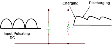
In this filter a capacitor is connected across the load during the rise of the voltage cycle it gets charged and this charge and this charge and thus the repel is reduced across the load, It is shown in the above Figure. It is popular because it’s a low cost, small size, less weight, and good characteristics Useful for load up to 50mAas in transistor radio battery eliminators.
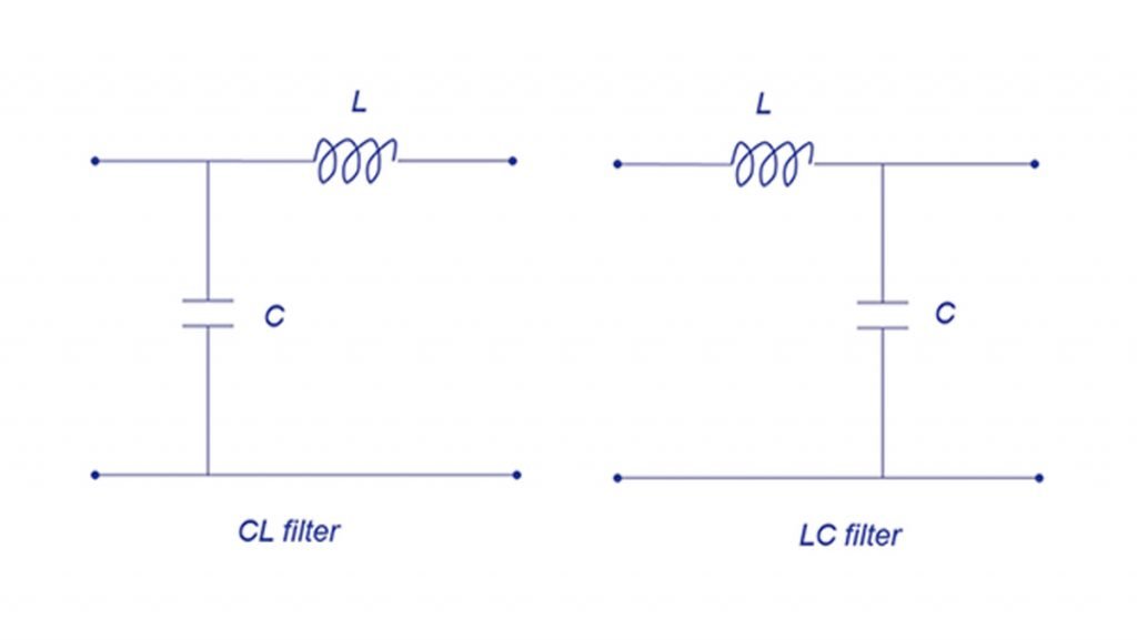
In the inductor filter, the ripple factor is directly proportional to the load resistance. On the other hand in a Capacitor, the ripple factor will become almost independent of the load filter. It is also known as an inductor input filter, choke input filter, L input, or LC-section.
In this circuit, a choke is connected in series with the load. It offers high resistance to the AC components and allows the DC component to flow through the load. The capacitor across the load is connected in parallel which filters out any AC component flowing through the choke In this way the ripples are rectified and a smooth DC is provided with the load.
It consists of one inductor and two capacitors connected across its each and The three components are arranged in the shape of the Greek letter Pi. It is called a capacitor input Pi filter. The input capacitor C1 is selected to offer very low reactance to the repel frequency hence major parts of filtering are done by C1. Most of the remaining repels are removed by the combining action of L and C2. This circuit gives a much better filter than an LC filter. However, C1 is still directly connected across the supply and would need a high pulse of current if the load current is large. This is used for the low current equipment.